3D-Bridge – Transferring of Cultural Heritage with New Technology:
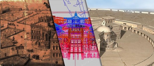
Visualization of Filippo Juvarra’s Palace Project and Garden Plan from 1705
Story Episodes
- Introduction
- Project Outline
- The Sources
- Construction Records: The plans (this post)
- Construction Records: The bird’s eye view
- Online Movie
- Download of the original computer model
- Partner Institutes
4. Construction Records: The plans
Comparison Of The Two Palace Plans
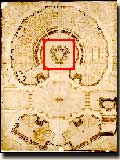
Icon of original plan.
|
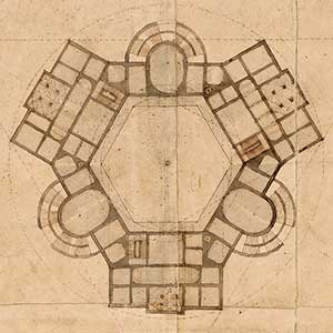
Detail of the plan |
The above plan ASL140 of the whole site shows an abstracted plan of the storeys of the palace. Its clarity facilitates our understanding of the inner structure of the building. It was not intended to be seen in detail. The intention was that it should still be comprehensible when viewed in a presentation to a larger public at a distance of several meters.
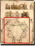
Icon of original plan.
|
Detail of the plan
|
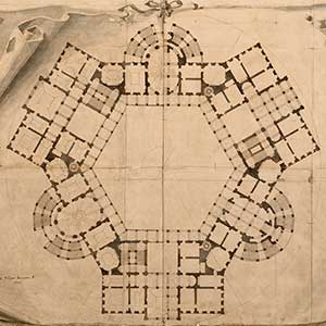
The plan ASL141 clarifies the variety of room relations to each other and the wealth of the architectural articulation of the design. Each stair, column, window and door is presented; even the shape of the individual ceiling vaults is established here.
The left side shows the first upper floor (Piano Nobile), the right side shows the ground floor (Piano Terra).
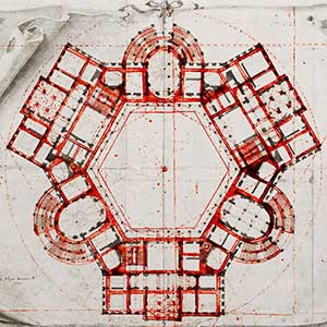 |
Here you see an overlay of both plans on the same scale: ASL140 in red, ASL141 in black.
As you can clearly see, at no point do both plans exactly coincide!
I therefore decided to deduce the basic design principles from both plans and to examine them side-by-side. Questions of detail, however, will only be clarified with ASL141, since this plan is more accurate and shows more detail. ASL140 on the other hand shows the geometric basic idea of the plan more clearly.
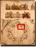
Icon of original plan.
|
|
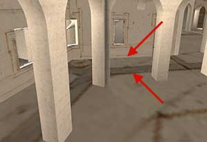
The lack of coincidence between the two plans means that the palace model cannot be exactly superimposed over the larger plan. This “error” can in fact be perceived also in the CAD model, where the palace model, modeled from the plan ASL141, stands on the ground, which shows the plan ASL140. The picture on the left shows this in detail. The two arrows show the wall of the courtjard. On the floor the map of ASL140, the model build with ASL141.
This text is an excerpt of my construction record.
